Below is the network setup on which we will configure FortiGate SD-WAN with load balancing for two different ISPs.
Parameters which we have taken are
- LAN Port & Segment -> LAN Port 3 & 10.10.10.108
- WAN Port -> WAN1 -> ISP1
- WAN Port 2-> ISP 2
- WAN Port 1 Segment -> 192.168.0.108
- WAN Port 2 Segment -> 14.140.40.108
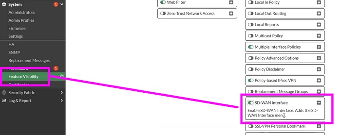
1. Enable SD-WAN feature in FortiGate
Go to Feature Visibility option and select SD-WAN Interface. You must enable this feature to configure SD-WAN interfaces in the firewall.
- System ->Feature Visibility
- Select -> SD-WAN Interface
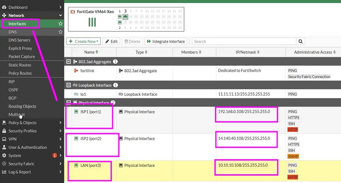
- Configure Interfaces as per above network diagram.
- Here, we have configured ISP1 (Port1)-> 192.168.0.108/24
- ISP2 (Port2) ->14.140.40.108/24
- Configure LAN port on port 3 (for downstream Switch)
2. Create SD-WAN Zone
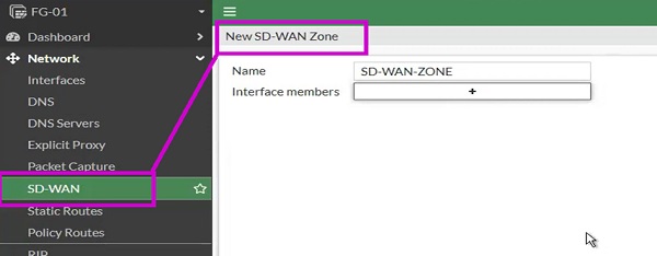
- Create SD-WAN Zone
- Named as SD-WAN-Zone
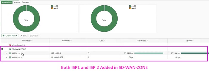
- Put WAN1 (ISP-1) and WAN2 (ISP-2) interfaces in it
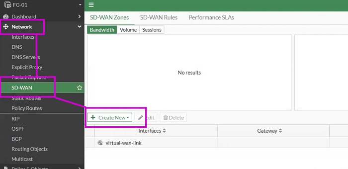
- SD-WAN->Select SD-WAN-ZONE
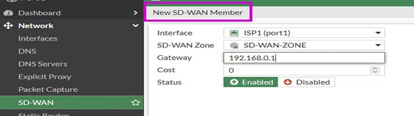
- Create New ->SD-WAN-Member
- Add ISP-1 Values
- Interface-> ISP1 (port1)
- SD-WAN-Zone-> SD-WAN-ZONE
- Gateway-> 192.168.0.1
- Status-> Enable
- OK
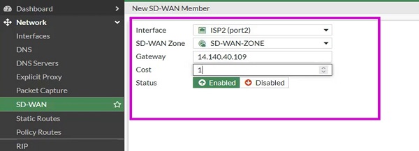
In a similar way add ISP2 in SD-WAN-Zone member
- Interface->ISP2(port2)
- SD-WAN-ZONE (Zone must be same in both member 1 and member 2)
- Gateway-> 14.140.40.109
- Cost-> 1
- Status -> Enable
- OK
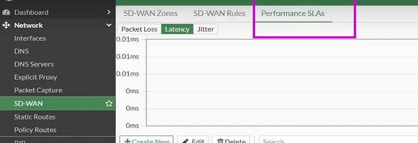
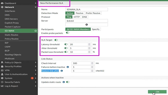
3. Configure Performance SLA
Next move to configure Performance SLAs Policy.
- Select -> SD-WAN
- Go to -> Performance SLAs
- Select-> Create New and add values in the tab
- Name-> SDWAN_SLA
- Detection Mode-> ACTIVE
- Protocol -> PING
- Server -> DNS Server/ Global DNS IP -> 8.8.8.8
- Enable SLA Target and put values in it
- Add values to Link Status
- Click OK
SLA Targets
- Latency Threshold -> maximum latency a link can manage to make decision
- Jitter Threshold ->Jitter for SLA to make the decisions
- Packet Loss Threshold->how much packet can loss when SD-WAN select SLA
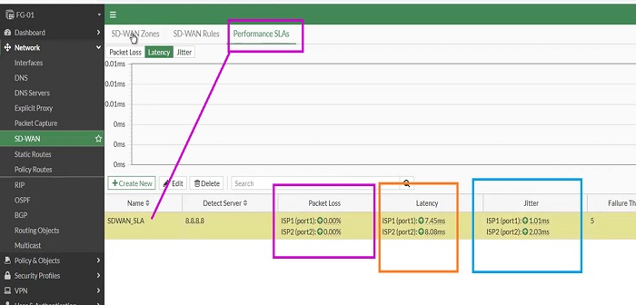
Performance SLA shown in below diagram which contains values of both ISP1 and ISP2
- Packet loss percentage of ISP1 and ISP2
- Latency data of ISP1 and ISP2
- Jitter values of ISP1 and ISP2
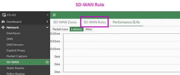
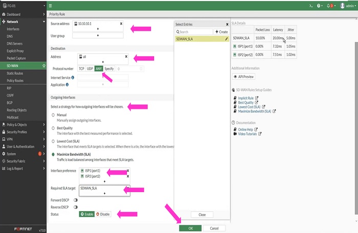
4. Configure SD-WAN Rules
- Go to SD-WAN ->SD-WAN Rules
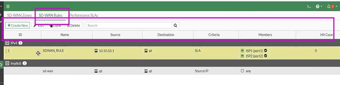
- Source-Address -> LAN IP Gateway
- Destination -> Allow for ALL
- Protocol -> TCP/UDP or ANY
- Select strategy for how outgoing interfaces will be chosen
Manual: We can manually send traffic to any specific interface and provide preference to that particular WAN interface. However only one WAN interface can take part in Performance SLA and another WAN interface (example -WAN2) act as a backup link.
Best Quality: Decision based on Cost factor of link. SD-WAN will choose best link to forward the application traffic. For example, Management traffic is critical which means it should come under Best Quality option and must be forwarded to Best ISP link where latency and delay factors are low.
Lowest Cost: SLA preference goes to Lowest link. SD_WAN choses lowest link which forwards traffic to match the SLA.
Maximise Bandwidth (SLA): Traffic distributed among the available links however, load-balancing and transfer of traffic takes place after matching Latency parameter of link. By default, it uses the Round-Robin method.
- We have selected Maximum Bandwidth
- Interface Preferences -> Select Both port of ISP1 and ISP2
- Status -> Enable
- OK
5. Configure Static Routes
Now, it’s turn to configure static routes for the destination subnet. Here we have configured static routes from all internal subnets by SD-WAN interface.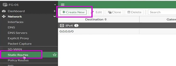
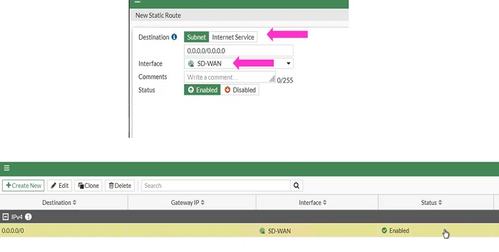
- Create New Static Route Rule
- Destination ->0.0.0.0/0 or All
- Interface -> SD-WAN
- Status -> Enable
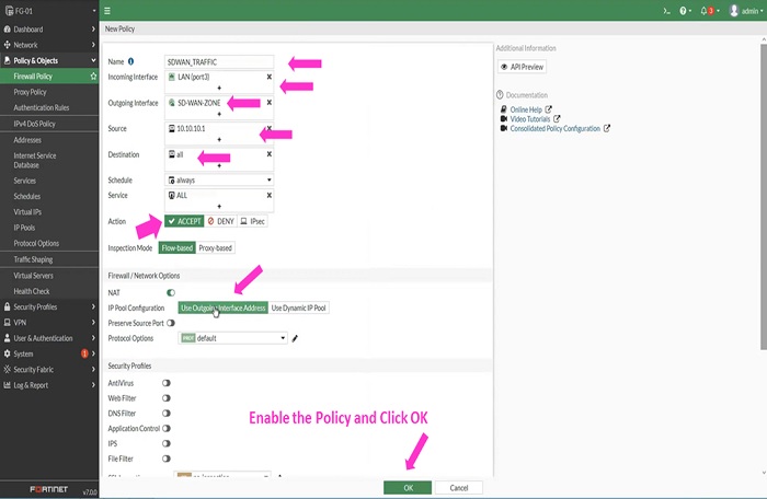
6. Firewall Policy
- Create Firewall policy to the Internet to allow LAN-to-WAN traffic.
- Name-> Add Policy Name
- Incoming Interface -> LAN (Port-3)
- Outgoing Interface -> SD-WAN
- Source IP Address -> LAN Subnet
- Destination -> ALL
- Service-> ALL
- Action-> Accept
- IP Pool Configuration -> Use Outgoing Interface Address
- OK
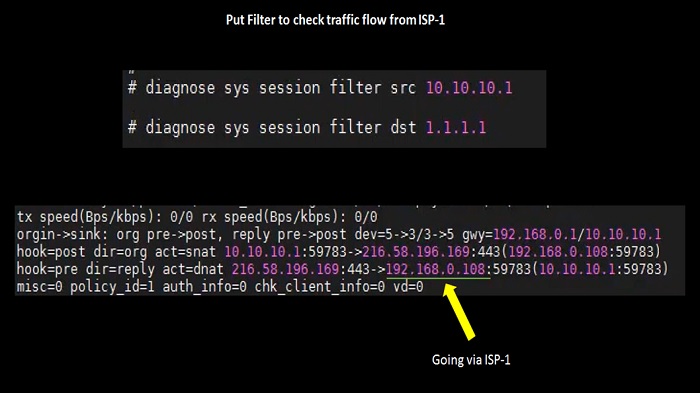
- Check Traffic stream from Firewall CLI.
- As per below logs traffic is going via ISP-1
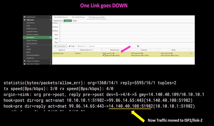
Troubleshoot ISP1 and ISP2 Failover
After enabling diagnosis logs in FortiGate CLI we have found that all the traffic moves to ISP-2
Load Balancing Algorithms
By default, SD-WAN uses the Round-Robin method to forward the traffic. However, we can change the selection of traffic by using different load-balancing traffic algorithms.
Two points must have been considered before selecting Load-balancing Algorithms
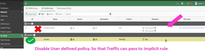
- We cannot apply Load-balancing algorithms on user defined policy
- Load-Balancing algorithms are applicable for implicit SD-WAN policies.
Let’s discussion the Algorithms in FortiGate Firewall (Version 7.0.0)
Load-Balancing modes and their definition:
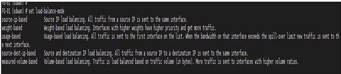
- Source-IP-based ->Traffic is divided between WAN1 and WAN2 equally however session which starts communication from ISP1 will stick to same ISP till the end.
- Weight-based -> Percentage of sessions that are allowed are calculated by using weight parameter which is assigned to each interface. Then sessions are distributed to each interface accordingly.
- Usage-based -> threshold set on Ingress and Egress interface and distribution of sessions happens according to the percentage defined on each Ingress and Egress interfaces.
- Source-destination-IP-based -> Same source IP goes to same destination through-out the session. Means, the same source address sticks to the same destination.
- Measure-volume-based -> Volume weight is calculated by assigning weight to each interface and sessions are divided accordingly.
First, disable User based policy in SD-WAN-Rules. Load-Balancing is only applied to implicit rules.
#set load-balance-mode source-ip-based >>>>>>>>>>>>>>> CLI Configuration
Other methods are explained in Web-UI Format
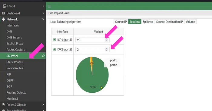
Load Balancing Algorithm- Weight Based
- Select SD-WAN
- Select Implicit policy
- Edit Implicit Policy
- Select Sessions tab to enable weight-based Algorithm for load-balancing
- Weight is divided here 98:2
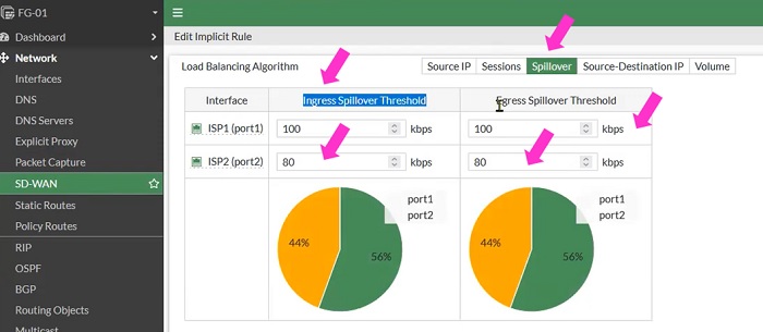
Load Balancing Algorithm- Usage Based
- Select SD-WAN
- Select Implicit policy
- Edit Implicit Policy
- Select Sessions tab to enable usage-based Algorithm for load-balancing. This is also known as Spillover method
- Traffic is divided between Ingress and Egress interfaces.
Load Balancing Algorithm- Volume Based
In our network we will use VOLUME based selection of traffic.
- Select SD-WAN
- Select Implicit policy
- Edit Implicit Policy
- Select Volume tab to enable Volume-based Algorithm for load-balancing
- Weight is divided here 90:10
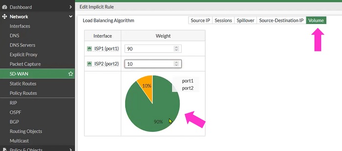
When checked traffic in cli, 90% of traffic moves to ISP1 and 10% moves to ISP2
Most of the traffic has a destination IP of ISP1.
No comments:
Post a Comment