Objectives
- IPSec
- IKE
- Site to Site VPN between two FortiGate Sites
- Phase I and Phase II Parameters
- Tunnel Configuration
- Troubleshooting Commands
IPSec VPN Configuration: Fortigate Firewall
IPsec: It is a vendor neutral security protocol which is used to link two different networks over a secure tunnel. IPsec supports Encryption, data Integrity, confidentiality.
IPsec contains suits of protocols which includes IKE.
IKE is used to authenticate both remote parties, exchange keys, negotiate the encryption and checksum that is used in VPN Tunnel. IKE uses port 500 and USP 4500 when crossing NAT device.
IKE allows two remote parties involved in a transaction to set up Security Association.
Security Association are basis for building security functions into IPsec. IPsec parameters like encryption algorithm, authentication methods, Hash value, pre-shared keys must be identical to build a security association between two remote parties.
Site To Site VPN Between FortiGate FWs
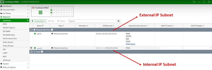
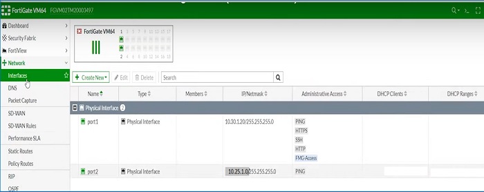
Firewall -1, check internal interface IP addresses and External IP addresses
IPSec VPN Configuration Site-I
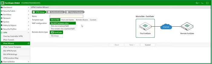
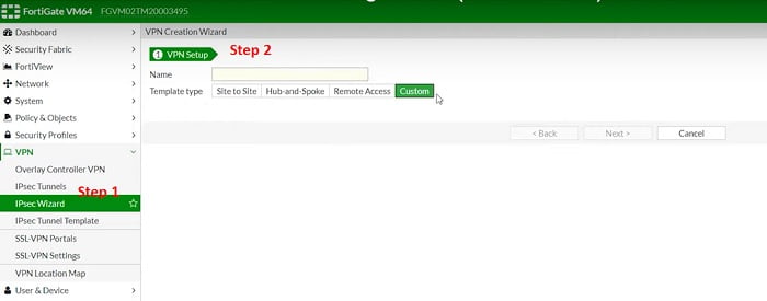
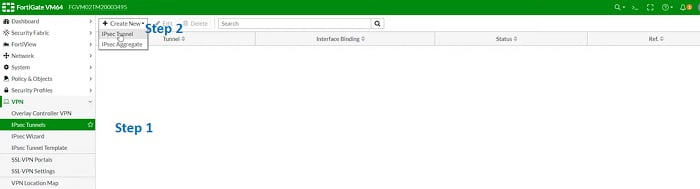
Follow below steps to Create VPN Tunnel -> SITE-I
1. Go to VPN > IPSec WiZard
2. Select VPN Setup, set Template type Site to Site
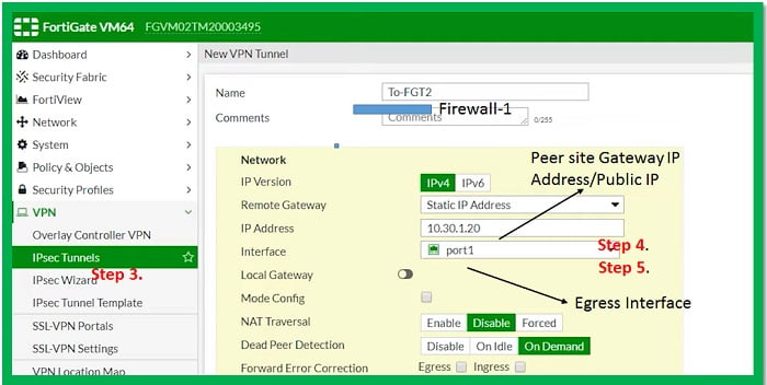
3. Name – Specify VPN Tunnel Name (Firewall-1)
4. Set address of remote gateway public Interface (10.30.1.20)
5. Egress Interface (Port 5)
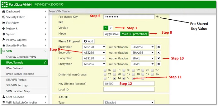
6. Enter Pre-shared Key, Pre-shared key is used to authenticate the integrity of both parties. It must be same on both sides.
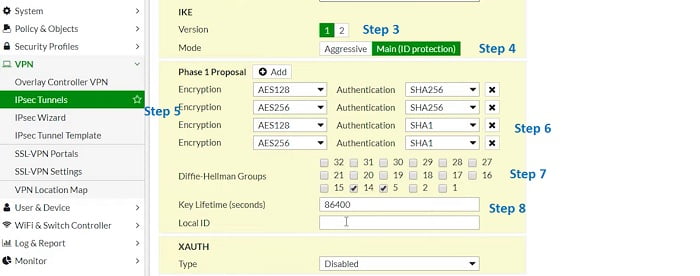
7. Select IKE version to communicate over Phase I and Phase II
8. Mode of VPN – Main mode/Aggressive Mode. Main mode is the suggested key-exchange method because it hides the identities of the peer sites during the key exchange.
9. Encryption Method, it must be identical with remote parties. Encryption method provides end-to-end confidentiality to the VPN traffic.
10. Authentication method – it must be identical with remote site. Authentication methods verify the identity of peer user which means traffic is coming from correct user and there is no man-in-middle attack.
11. DH Group- Must be identical with remote peer (DH-5). Diffie-Helliman is a key exchange protocol and creates a secure channel by exchanging public key /master key.
12. Key Lifetime – it defines when re-negotiation of tunnels is required. Key lifetime should be identical. However, if the lifetime of key mismatched then it may lead to tunnel fluctuations.
VPN Phase-II
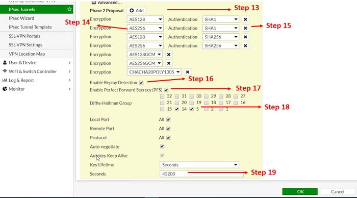
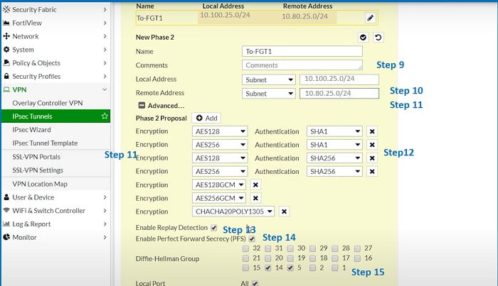
13. Add Phase II proposals
14. Select Encrytpion method AES256
15. Select Authentication method SH-I
16. Enable Anti-Replay Detection è Anti-replay is an IPSec security method at a packet level which helps to avoid intruder from capturing and modifying an ESP packet.
17. PFS (Enable Perfect Forward Secrecy)-Must be enabled at both peers end,
18. DH Group- Select 5
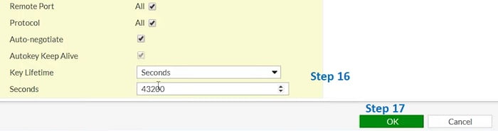
19. Key lifetime for Phase II
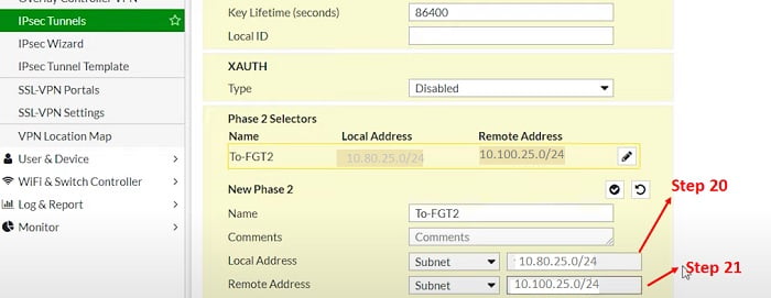
Phase II Selector
20. Share Local LAN subnet which will communicate once VPN is established
21. Share remote end LAN subnet
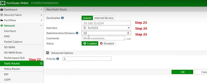
Create Static Route towards VPN Tunnel Interface
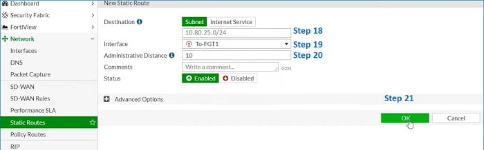
22. Static Route
23. Local LAN subnet going via Tunnel Interface To-FG-2
24. Allocate Tunnel Interface
25. Assign Administrative distance 10 (static Routes)
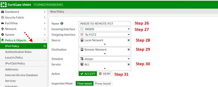
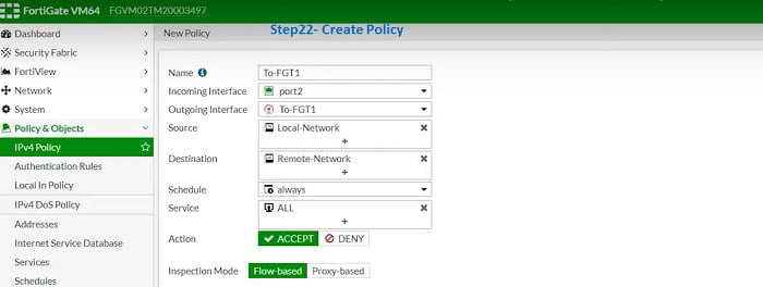
Create VPN- Policy for interesting traffic & allow ports according to requirement
26. Assign name to the policy in IPV4 Policy Tab
27. Traffic incoming from Inside Zone/Interface and Outgoing Interface will be Tunnel Interface
28. Source address which will be 80.25.0/24
29. Destination address will be remote site Local LAN subnet 10.100.25.0/24
30. Services/protocol – select all or you can select specific servuces like FTP/HTTP/HTTPS
31. Accept the action.
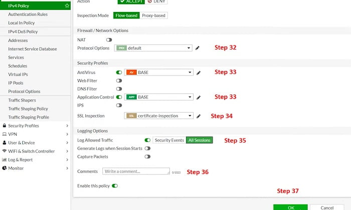
32. NAT is OFF and Protocol Options are Default
33. Basic Anti-Virus has been enabled and Basic Application Control is enabled
34. SSL Certificate is enabled to authenticate over SSL Inspection/ Its completely optional
35. Enable ALL session logs
36. Add Policy Comment and Enable the Policy
37. Select OK
**If requires, create a reverse clone policy for the connection to enable bi-direction action.
From Step 1 to Step 37, VPN configuration has been completed for Firewall -1/Site-1.
Let’s move to Firewall -2/Site II
- Check Internal and External Interface IP address and Ports
IPSec VPN Configuration Site-II
Start following step-1 to step-22 to complete the VPN configuration in Firewall-2.
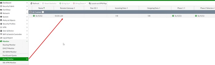
- Monitor VPN traffic status in IPSec Monitor TAB for further Troubleshooting.
Troubleshooting Commands
Run debug and basic troubleshooting commands if tunnel status in not showing or visible in IPSec Monitor TAB,
Debug commands:
# diag vpn tunnel list
# diag vpn ike filter clear
# diag vpn ike log-filter dst-addr4 x.x.x.x <—– remote peer Public IP
# diag debug application ike -1
# diag debug console timestamp enable
# diag debug enable
Initiate the connection and try to bring up the tunnel from GUI
(VPN -> IPsec Monitor -> Bring UP ):
# diagnose vpn tunnel up “vpn_tunnel_name” <—– Check packets of Phase I
Disable the Debug to stop packets
# diag debug disable
# diag debug reset
No comments:
Post a Comment