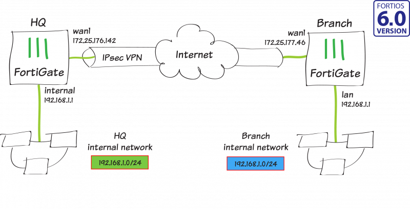
In this recipe, you create a route-based IPsec VPN tunnel, as well as configure both source and destination NAT, to allow transparent communication between two overlapping networks that are located behind different FortiGates.
In this example, one FortiGate will be referred to as HQ and the other as Branch. They both have 192.168.1.0/24 in use as their internal network (LAN), but both LANs need to be able to communicate to each other through the IPsec tunnel.
Planning the new addressing scheme
In order for overlapping subnets to be able to communicate over a route-based IPsec tunnel, new virtual subnets of equal size must be decided upon and used for all communication between the two overlapping subnets.
Devices on both local networks DO NOT need their IP addresses changed. However, the devices/users will need to be sure to use the new subnet range of the remote network when communicating across the tunnel. |

In this example, you perform a one-to-one mapping of HQ’s 192.168.1.0/24 network to 10.1.1.0/24, and Branch’s 192.168.1.0/24 network to 10.2.2.0/24. This will allow HQ clients to use Branch’s new subnet to communicate to Branch clients, and vice-versa.
Configuring the IPsec VPN on HQ
- To create the tunnel on HQ, connect to HQ and go to VPN > IPsec Tunnels.
- In the VPN Setup step, set Template Type to Custom and enter VPN-to-Branch for the Name.

- Enter Branch’s public IP address (in the example, 172.25.177.46) for the IP Address, and select HQ’s WAN interface for Interface (in the example, wan1).

- Enter a secure key for the Pre-shared Key. Later, you will enter the same key in the "Configuring the IPsec VPN on Branch" section.

- Type the new address ranges selected in the "Planning the new addressing scheme" section for HQ and Branch’s LAN in the Local Address and Remote Address fields (in the example, 10.1.1.0/24 and 10.2.2.0/24, respectively).

- Optionally, expand Advanced and enable Auto-negotiate.

Configuring static routes on HQ
- To create the necessary routes on HQ, go to Network > Static Routes and select Create New.
- Enter the new subnet created in the "Planning the new addressing scheme" section for Branch’s LAN in the Destination field, and select the VPN tunnel created in the "Configuring the IPsec VPN on HQ" section as the Interface (in the example, this is 10.2.2.0/24 and VPN-to-Branch).

- Create an additional route with the same Destination as the previous route, but this time change the Administrative Distance to 200 and select Blackhole as the Interface. This is the best practice for route-based IPsec VPN tunnels, as it ensures traffic for the remote FortiGate's subnet is not sent using the default route in the event that the IPsec tunnel goes down.

Configuring address objects on HQ
- To create address objects you will utilize in a later step, navigate to Policy & Objects > Addresses and select Create New > Address.
- Enter HQ-original for the Name, the original LAN subnet of HQ for Subnet (in the example, 192.168.1.0/24), and select the LAN-side interface for Interface (in the example, internal).

- Repeat the process to create an additional new address object.
- Enter Branch-new for the Name, the new LAN subnet of Branch for Subnet (in the example, 10.2.2.0/24), and select the VPN interface for Interface (in the example, VPN-to-Branch).

- To create an IP Pool, navigate to Policy & Objects > IP Pools and select Create New.
- Enter HQ-new for the Name and select Fixed Port Range for Type. For the External IP Range enter the new subnet for HQ (in the example, 10.1.1.1 – 10.1.1.254). You do not need to include the network address or the broadcast address for the subnet in the External IP Range of the IP Pool. For the Internal IP Range, enter the original subnet for HQ (in the example, 192.168.1.1 – 192.168.1.254).

- Finally, to create a Virtual IP, navigate to Policy & Objects > Virtual IPs and select Create New > Virtual IP.
- Enter HQ-new-to-original for the Name and select the VPN interface for Interface (in the example, VPN-to-Branch). For the External IP Address/Range enter the new subnet for HQ (in the example, 10.1.1.1 – 10.1.1.254). You do not need to include the network address or the broadcast address for the subnet in the External IP Range of the Virtual IP. For the Mapped IP Address/Range, enter the original subnet (in the example, 192.168.1.1 – 192.168.1.254).

Configuring firewall policies on HQ
- To create firewall policies on HQ, go to Policy & Objects > IPv4 Policies and select Create New.
- Enter From-HQ-to-Branch for the Name, the LAN-side interface on HQ for Incoming Interface (in the example, internal), and the VPN tunnel interface for Outgoing Interface (in the example, VPN-to-Branch).

- For the Source, select HQ-original, for the Destination select Branch-new, and for the Service select ALL.
- Finally, enable NAT, select Use Dynamic IP Pool, and select the HQ-new IP Pool.
- Repeat the process to create an additional new IPv4 Policy.
- Enter From-Branch-to-HQ for the Name, the VPN interface for Incoming Interface (in the example, VPN-to-Branch), and the LAN-side interface for Outgoing Interface (in the example, internal).

- For the Source, select Branch-new, for the Destination select HQ-new-to-original (the Virtual IP object you created in the "Configuring static routes on HQ" section), and for the Service select ALL.
- Note for this policy, you do not need to enable NAT.
Configuring IPsec VPN on Branch
- To create the tunnel on Branch, connect to Branch, and go to VPN > IPsec Tunnels and create a new tunnel.
- In the VPN Setup step, set Template Type to Custom and enter VPN-to-HQ for the Name.

- Enter HQ’s public IP address (in the example, 172.25.176.142) for the IP Address, and select Branch’s WAN interface for Interface (in the example, wan1).

- Enter a matching secure key for the Pre-shared Key.

- Type the new address ranges selected in the "Planning the new addressing scheme" section for Branch and HQ’s LAN in the Local Address and Remote Address fields (in the example, 10.2.2.0/24 and 10.1.1.0/24, respectively). The Local and Remote Address fields are the reverse of what you created in the "Configuring the IPsec VPN on HQ" section.

- Optionally, expand Advanced and enable Auto-negotiate.
Configuring static routes on Branch
- To create the necessary routes on Branch, go to Network > Static Routes and select Create New.
- Enter the new subnet created in the "Planning the new addressing scheme" section for HQ’s LAN in the Destination field, and select the VPN tunnel created in the "Configuring the IPsec VPN on Branch" section as the Interface (in the example, this is 10.1.1.0/24 and VPN-to-HQ).

- Create an additional route with the same Destination as the previous route, but this time change the Administrative Distance to 200 and select Blackhole as the Interface.

Configuring address objects on Branch
- To create address objects you will utilize in a later step, navigate to Policy & Objects > Addresses and select Create New > Address.
- Enter Branch-original for the Name, the original LAN subnet of Branch for Subnet (in the example, 192.168.1.0/24), and select the LAN-side interface for Interface (in the example, lan).

- Repeat the process to create an additional new address object.
- Enter HQ-new for the Name, the new LAN subnet of HQ for Subnet (in the example, 10.1.1.0/24), and select the VPN interface for Interface (in the example, VPN-to-HQ).

- To create an IP Pool, navigate to Policy & Objects > IP Pools and select Create New.
- Enter Branch-new for the Name and select Fixed Port Range for Type. For the External IP Range enter the new subnet for Branch (in the example, 10.2.2.1 – 10.2.2.254), and enter the original subnet for Branch in the Internal IP Range (in the example, 192.168.1.1 – 192.168.1.254).

- Finally, to create a Virtual IP, navigate to Policy & Objects > Virtual IPs and select Create New > Virtual IP.
- Enter Branch-new-to-original for the Name and select the VPN interface for Interface (in the example, VPN-to-HQ). For the External IP Range enter the new subnet for Branch (in the example, 10.2.2.1 – 10.2.2.254), and enter the original subnet for Branch in the Internal IP Range (in the example, 192.168.1.1 – 192.168.1.254).

Configuring firewall policies on Branch
- To create firewall policies on Branch, navigate to Policy & Objects > IPv4 Policies and select Create New.
- Enter From-Branch-to-HQ for the Name, the LAN-side interface on Branch for Incoming Interface (in the example, lan), and the VPN tunnel interface for Outgoing Interface (in the example, VPN-to-HQ).

- For the Source, select Branch-original, for the Destination select HQ-new, and for the Service select ALL.
- Finally, enable NAT, select Use Dynamic IP Pool, and select the Branch-new IP Pool.
- Repeat the process to create an additional new IPv4 Policy.
- Enter From-HQ-to-Branch for the Name, the VPN interface for Incoming Interface (in the example, VPN-to-HQ), and the LAN-side interface for Outgoing Interface (in the example, lan).

- For the Source, select HQ-new, for the Destination select Branch-new-to-original (the Virtual IP object you created in the "Configuring address objects, Virtual IPs, and IP Pools on Branch" section), and for the Service select ALL.
- Note for this policy, you do not need to enable NAT.
Results
- The IPsec tunnels should now be up on both sides, which you can verify under Monitor > IPsec Monitor. If you did not enable auto-negotiate in the "Configuring the IPsec VPN on HQ" section or "Configuring the IPsec VPN on Branch" section earlier, then you may have to highlight the tunnel and select Bring Up.

- From a PC on the HQ network, try to ping a PC on the Branch network using the new IP for the Branch PC. The ping should be successful.
- From a PC on the Branch network, try to ping a PC on the HQ network using the new IP for the HQ PC. The ping should be successful.
Explanation
Using the two example PCs below, the source and destination NAT that is performed in order to allow these two PCs in overlapping subnets to communicate is explained.

Step 1 – Ping Request: HQ Test PC sends a ping destined for Branch Test PC’s new IP address of 10.2.2.98.
Src IP: 192.168.1.12
Dst IP: 10.2.2.98
Step 2 – Source NAT: The HQ FortiGate receives the ping, and after a route lookup, matches the traffic to firewall policy From-HQ-to-Branch that you created in the "Configuring firewall policies on HQ" section of the recipe.
Since the policy has NAT enabled and the HQ-new IP Pool selected, the HQ FortiGate will perform source NAT on HQ Test PC’s IP address before sending into the IPsec tunnel.
Src IP: 10.1.1.12
Dst IP: 10.2.2.98
When you created an IP Pool with Type of Fixed Port Range, and then selected an External IP Range and Internal IP Range of equal size, the last octet of the IP addresses after SNAT will not change. This means 192.168.1.12 will be changed to 10.1.1.12, which makes using the new address range as simple as possible. |
Step 3 – Destination NAT: Branch FortiGate receives the traffic on the IPsec tunnel, and before a policy is matched, the Virtual IP (VIP) you created called Branch-new-to-original performs destination NAT (DNAT).
Similar to our Fixed Port Range IP Pool, a VIP will exactly map the External IP Range to the Mapped IP Range. This means that 10.2.2.98 will DNAT to 192.168.1.98. |
After DNAT, a route lookup is performed, and the traffic will match the From-HQ-to-Branch policy that you created in the "Configuring firewall policies on Branch" section of the recipe.
Src IP: 10.1.1.12
Dst IP: 192.168.1.98
Step 4 – Ping Reply: Branch Test PC receives the ping request from HQ Test PC and sends the ping reply back to 10.1.1.12.
The FortiGate is a stateful firewall, and the same firewall policy that was used when the session was initiated will be used on the way back (the From-HQ-to-Branch policy on both FortiGates).
The session table on each FortiGate remembers the SNAT or DNAT that was performed in the "Configuring the IPsec VPN on HQ" section and "Configuring static routes on HQ" section, and will perform the reverse operation on the reply traffic.
Src IP: 192.168.1.98
Dst IP: 10.1.1.12